Before replacing a fuel pump, you should check all of the wiring and the electrical contacts. Often, the fuel pump is not broken and only the connections are faulty. How are the system pressure and volumetric flow of the fuel pump measured? Where exactly is the voltage at the fuel pump measured? In this TechTip, Pierburg gives you the answers.
In the event of problems in the fuel system, the system pressure and volumetric flow of the fuel pump should be measured first. If the measured values do not match the manufacturer’s specifications, it is sometimes the case that the supposedly faulty fuel pump, is replaced with a new one prematurely.
Before you replace a pump, you should ensure that a corroded electrical connection is not the cause of loss of power. Depending on the flow rate and system pressure, the current consumption of a fuel pump is 5-8 amps or more. In the case of such high currents, clean and reliable contact points are important, since any type of corrosion or poor contacts increase the resistance across the contact.
However, increased resistance necessarily means a drop in voltage at the fuel pump. The typical circuit of a fuel pump has a number of detachable connections, due to screwed-in or plugged-in contacts. In addition, there are switching contacts within the ignition switch and the fuel pump relay, as well as possible additional installations in the system, such as anti-theft devices.
Each of these contacts may have increased resistance due to oxidation, corrosion and an inadequate connection. This results in a undesired drop in voltage in this circuit. A drop in voltage may result in lack of proper performance of the fuel pump. The consequences are a reduction in pressure and flow rate.
In-Tank Fuel Pumps In modern vehicles, the fuel pump is located in the fuel tank, and usually takes the form of a fuel delivery module. In this case, it is difficult to carry out measurements directly at the terminals of the fuel pump. However, it is necessary that the drop in voltage is measured as close as possible to the fuel pump. It is therefore recommended that measurement is carried out at the electrical plug contacts, which are usually located in the cover of the fuel delivery module.
It is only possible to receive a correct result if the circuit is closed, i.e. when voltage is present. For this reason, you have to keep the engine running during measurements.
Loss at the contacts is unavoidable, even if the contacts are clean and tightly connected. The voltage at the terminals of the fuel pump is therefore always lower than the on-board voltage. The value should be as close as possible to the on-board voltage of the vehicle. However, the difference should not exceed 1 – 1.5 volts.
Regulated Fuel Pumps In modern vehicles that are equipped with a “regulated” or “demand-based” fuel supply, the fuel pump is actuated by its own control unit, with a pulse width modulation signal. A conventional digital multimeter is not sufficient to test these types of systems, as you simply measure the average voltage over a period here. In this case, you need an oscilloscope.
Recommended Procedure - Determine system pressure and flow rate
- Measure voltage drop at the fuel pump with the plug connected (Fig. 1).
- Connect the multimeter probes to the rear of the plug (Fig. 2).
- Never “puncture” the wires (Fig. 3)!
- A voltage of at least 12.5 – 13.0 volts must be present when the engine and pump are running.
- If the measured voltage at the terminals or the plug of the pump is significantly lower than the on-board voltage, e.g. lower than 11 volts, there is a malfunction.
- In this case, check the condition of all contacts in the circuit, e.g. to see whether corrosion is present at the contacts (Fig. 4).
To read more of this technical article or download the entire article click
here. There are lots more Tech Tips to view, and they are all searchable, on
TechTips.ie.
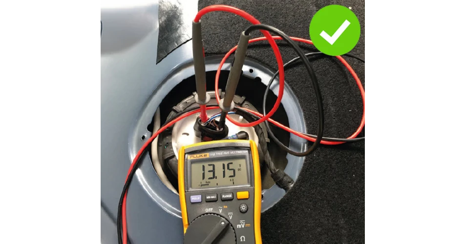 Voltage is checked at the cover of the fuel delivery module
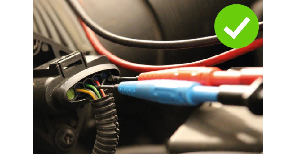 Measuring probes on the rear of the plug is the correct method
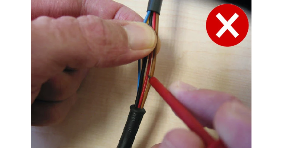 Piercing wiring is never recommended as it will lead to future corrosion and failure
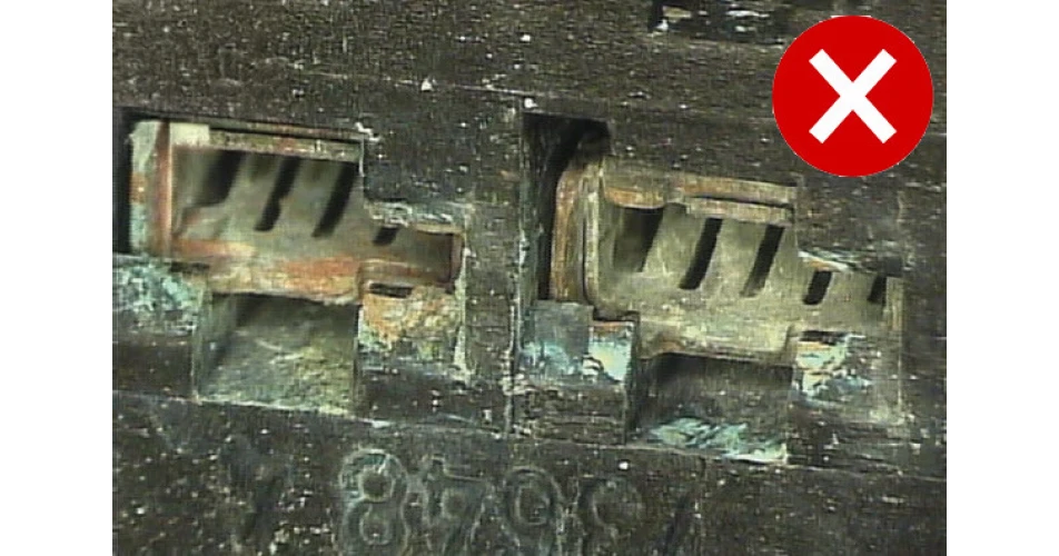 Corrosion on contacts of a connector will cause a failure


-1-1.jpg)


-1-1.jpg)


