REPXPERT Alistair Mason is looking at something a bit different, an Audi A4 2.0 TDI that has covered just over 114,000 miles. The A4 is fitted with a CVT Multitronic gearbox. The customer has reported that they can hear a rattling noise & would like it investigated.
When starting and stopping, the engine rattle was more pronounced, and at idle a light rattle could be heard. Using a “chassis ear” and the old-fashioned method of holding a long screwdriver to the ear, it was confirmed that the noise was coming from the bell housing area. The customer was advised that all the evidence indicated that the Dual Mass Flywheel (DMF) had come to the end of its service life, and that the gearbox would need to be removed and the customer authorized the work. The LuK DMF Part number is 415 0956 08. Repair time is 7.70 hours.
Initially this repair looks a little complicated, but when broken down, it is relatively straight forward and makes a great repair for any independent workshop.
Required workshop equipment - Vehicle lift, two post lift is preferred
- Transmission jack
- CVT/Multitronic gearbox oil filling tool
Note - the locking wheel bolt key is also required and this was requested to the customer.
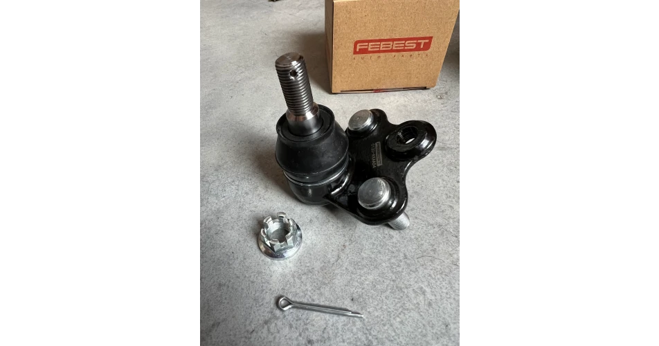
Gearbox removal With the vehicle placed in the lift, remove the ignition key and ensure the steering lock has activated. Open the boot, remove the spare wheel and disconnect the battery lead. Open the bonnet and raise the vehicle to waist height. Remove both front wheels and plastic drive shaft shields, this now gives us access to the driveshaft flange bolts which can now be removed and also the N/S driveshaft shield (Fig 1).
Raise the vehicle lift to gain access to the underside. Remove the engine and gearbox undertrays, disconnect the metal power steering pipe from the O/S subframe, remove the floor brace bars (Fig 2), and disconnect the steering column universal joint from the steering rack. Remove the anti-roll bar to subframe clamps, move the anti-roll bar down and then remove the two bolts that secure the steering rack (Fig 3) and then ease the steering rack down. This now gives access to the two starter motor bolts. Remove the two subframe heat shields, located by each driveshaft, as this gives us a little more space. Remove the front engine mounting, slacken the exhaust centre sleeve. Slide back to disconnect the exhaust and also remove the exhaust front pipe bracket (Fig 4).
Support the gearbox with a transmission jack, and remove the gearbox mounting assembly. Lower the gearbox slightly, disconnect the large multiplug on the back of the gearbox and remove the gear change cable. With a long extension, the upper bellhousing bolt can be removed. Place an oil drainer under the gearbox, and disconnect the oil pipes that go into the top of the gearbox on the O/S (Fig 5). Clamp the two oil pipes in front of the anti-roll bar on the N/S, disconnect and cap, if possible, to prevent leakage (Fig 6).
Remove the plastic plate at the bottom of the bellhousing and remove the three bolts that secure the DMF to the engine drive plate (Fig 7) to rotate the engine. Remove the rubber grommet from the bottom pulley, using a socket and bar, rotate the engine in 120-degree intervals to gain access to the bolts. Remove the rest of the bellhousing bolts, using a second transmission jack or support at the front of the engine. Ease the gearbox back, and when it is clear of the engine, carefully lower the transmission jack, keeping an eye on the steering rack and cooler pipes as the gearbox is being lowered. When fully clear, wheel the transmission jack clear of the vehicle.
DMF replacement We now need to remove the driveshaft from the gearbox. Rotate the gearbox so that the differential is closer to the floor, this will prevent oil leaking out of the differential when the driveshaft is removed. Remove the three bolts from the plate that retains the driveshaft (Fig 8) and the ease the driveshaft out of the gearbox. The DMF can then be lifted off the clutch input shaft and removed from the gearbox. Clean the bellhousing area, inspect the clutch input shaft for any wear. If all is ok, apply a light smear of high melting point grease to the splines of the clutch input shaft.
Looking at the removed DMF (Fig 9), there is no way these can be tested in the workshop. All we can do is carry out a visual inspection, and feel the rotation of the secondary mass. This flywheel did not feel smooth in operation, when compared to the new one.
Mount the new DMF onto the clutch input shaft, with the aid of the handle provided in the DMF kit, and support with the special tool also provided (Fig 10). The driveshaft can now be carefully inserted back into the gearbox and secured with the three bolts.
Gearbox installation Level the gearbox on the transmission jack, check all cables, wiring, etc. are clear on the back of the engine, and that the engine to gearbox alignment dowels are installed correctly. Carefully ease the gearbox into position.
When the gearbox is located on the alignment dowels, push the gearbox so it is fully against the engine, and install a couple of easily accessible bellhousing bolts and tighten. Installation is then in reverse order of removal.
After gearbox installation, remember to:
- Top up the gearbox oil
- After connecting the battery, reset all effected electrical consumers
- Always carry out an extended road test to ensure a quality repair
Full repair instructions, service information for this particular DMF and installation videos are available on Schaeffler’s REPXPERT portal.
Information on Schaeffler products, fitting instructions, labour times and much more can be found on the REPXPERT workshop portal - www.repxpert.co.uk - the REPXPERT app, or by calling the Schaeffler REPXPERT hotline on (+44) 1432 265 265.
To read more of this technical article or download the entire article click
here. There are lots more Tech Tips to view, and they are all searchable, on
TechTips.ie.
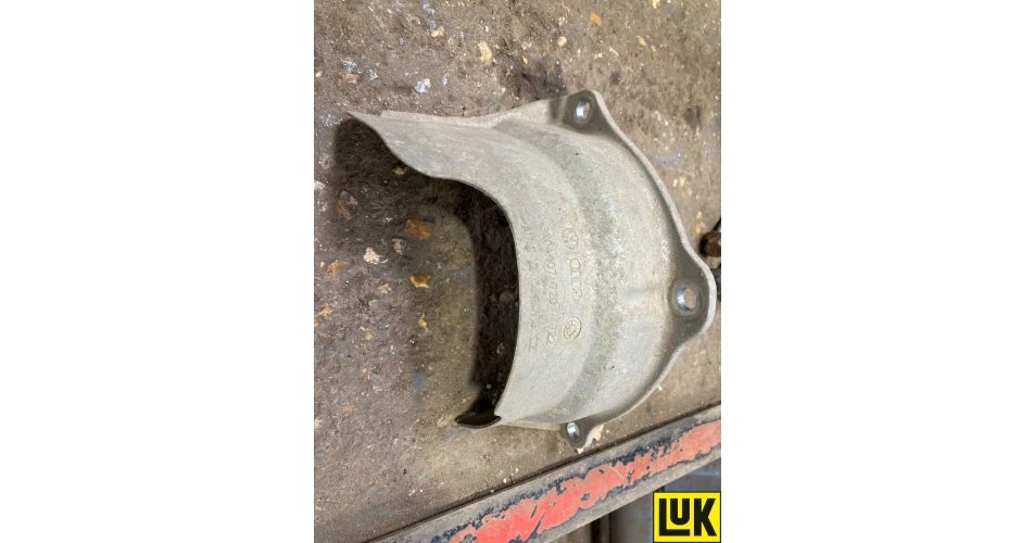 Fig 1
Fig 1
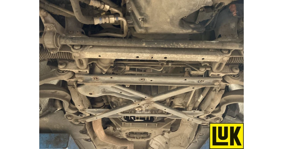 Fig 2
Fig 2
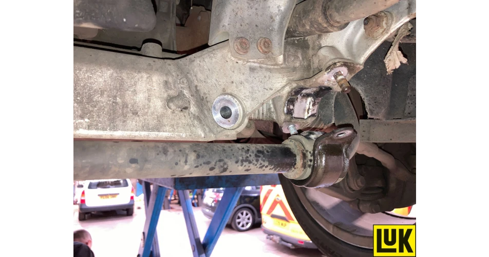 Fig 3
Fig 3
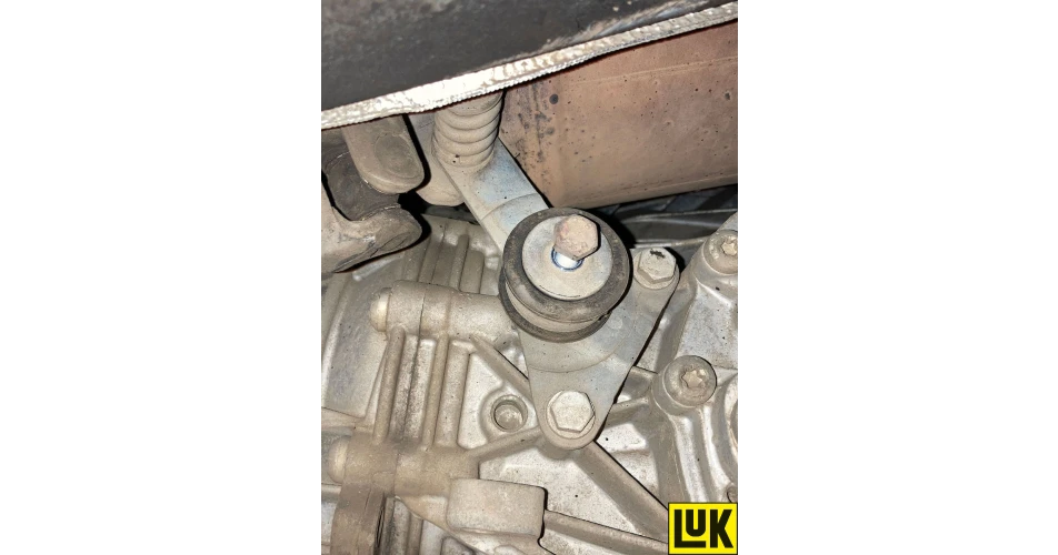 Fig 4
Fig 4
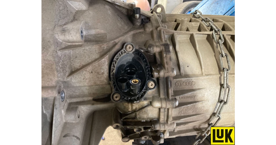 Fig 5
Fig 5
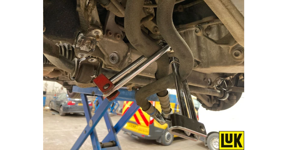 Fig 6
Fig 6
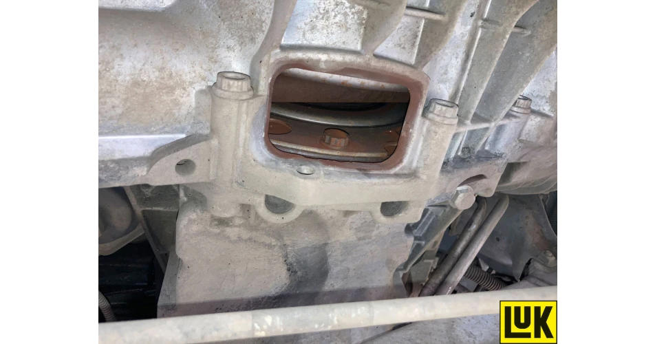 Fig 7
Fig 7
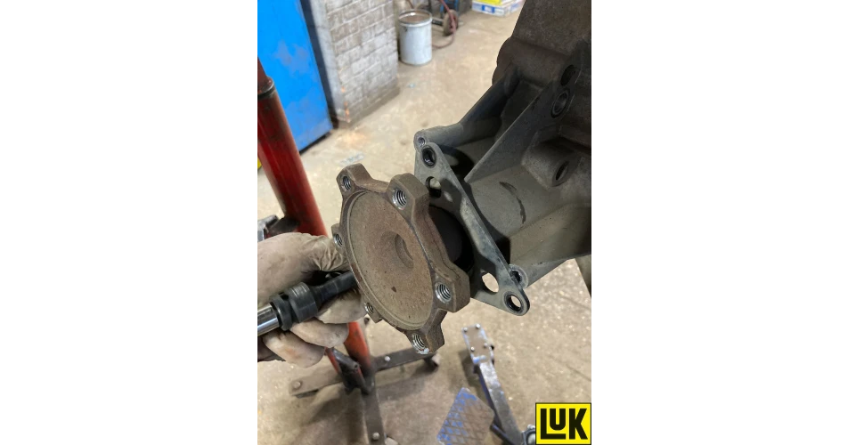 Fig 8
Fig 8
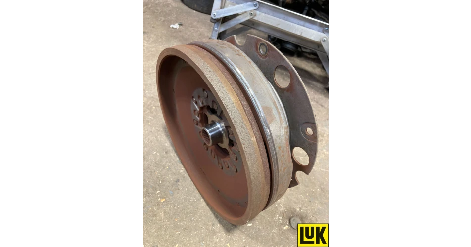 Fig 9
Fig 9
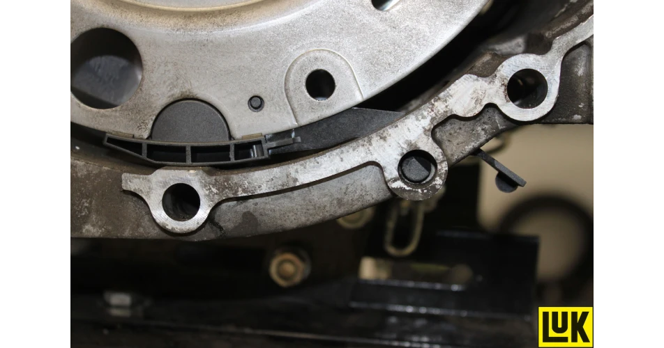 Fig 10