REPXPERT Alistair Mason is replacing the clutch on a 2019 Peugeot Partner van, fitted with a 1.6 HDi engine. The van has covered over 110,000 miles and the driver has reported that the clutch seems to be “slipping”. A short road test confirmed this. With a book time of 5.4 hours, and no specialist equipment required, this makes a great repair for any independent garage.
Workshop equipment required - Vehicle lift (two post is the ideal choice).
- Engine support.
- Transmission jack.
- Clutch alignment tool.
Prior to starting the repair, it is good practice to scan the QR code on the LuK clutch box (Fig. 1) using the REPEXPERT app.
Firstly, this will highlight if there is any service information relating to this product. It will also give you the repair instructions including torque settings, and not forgetting the bonus points that can be exchanged for goods in the bonus shop.
Gearbox removal With the vehicle on the lift, open the bonnet, disconnect and remove the battery (Fig. 2). You will have to unclip some wiring to aid battery removal. Remove the plastic tray that the battery sits on, and then unbolt the battery carrier and remove from the vehicle. This now gives good access to the top of the gearbox area.
The following items that can be removed: air ducting from front panel to air box assembly, gearbox earth strap, and reverse light switch multiplug. Unclip the loom, ease the wiring loom off the top bell housing bolts and then remove the top bell housing bolts and upper starter motor bolts. Disconnect the gear change cables (Fig. 3), and remove the accessible linkage bolts.
Raise the vehicle lift to waist height, and remove both front wheels, the N/S hub nut and the N/S wheel arch liner. Raise the lift to gain access to the underside, to remove the front subframe, by disconnecting both bottom ball joints and anti-roll bar links.
Unbolt the exhaust mounting and DPF sensor at the rear of the subframe (Fig. 4), then remove the lower gearbox pendulum mounting and steering rack retaining nuts. Secure the steering rack to the vehicle, to keep it in place when the subframe is removed.
Supporting the subframe with the transmission jack, remove all subframe mountings and remove the sub-frame from the vehicle.
Drain the gearbox oil and, whilst draining, disconnect the exhaust front pipe at the flexible joint.
Refit the oil drain plug and torque to the manufacture’s specification.
At the rear of the engine, remove the heat shield to gain access to the starter motor, remove the lower starter motor retaining bolts, support bracket, and then remove the lower bell housing bolts.
Remove the three retaining bolts from the O/S driveshaft support (Fig. 5). This will allow you to leave the driveshaft in position and ease the support housing out of the gearbox.
Remove the N/S driveshaft. Remove the two slave cylinder retaining bolts, and ease away from the gearbox, leaving the hydraulics connected.
Remove the nut and stud (Fig. 6) that secures the catalytic converter bracket to the engine block, with the use of a female Torx socket. This needs to be removed to gain access to a bell housing bolt, once removed, remove the bell housing bolt.
Supporting the engine with a suitable support, access the engine bay and remove the top gearbox mounting. Lower the engine and gearbox slightly to aid gearbox removal. Support the gearbox with a transmission jack and remove the final bell housing bolts.
Ease the gearbox away from the engine. Once the gearbox input shaft is clear of the clutch assembly, lower the gearbox on the transmission jack, and remove from the vehicle.
Clutch replacement Remove the six clutch retaining bolts and remove the clutch assembly.
At this point, the clutch problem was evident. The clutch had reached the end of its service life, as the lining had worn down to the rivets (Fig. 7).
Clean the face of the flywheel using emery cloth. This will also remove the glaze and then wash off with clutch and brake dust cleaner.
Inspect and replace the release system in the gearbox bell housing. Remove the release bearing and release arm. Inspect the ball pivot, release arm and bearing guide tube for any wear. In this instance, wear was evi-dent on the ball pivot and the release arm, so both were replaced with the customers authorisation.
Clean the bell housing area, removing all old clutch dust. Apply a light smear of high melting point grease to the guide tube and gearbox input shaft, and install the release system. Finally, mount the new clutch plate onto the input shaft. This will confirm it is the right fitment and also evenly distribute the grease. Remove the clutch plate and wipe off any excess grease.
Ensure the flywheel and clutch pressure plate are clean and degreased, using clutch and brake dust cleaner.
Using a clutch alignment tool (Fig. 8), mount the clutch plate onto the flywheel ensuring “gearbox side” is facing outwards.
Mount the clutch pressure plate onto the dowels, insert the six bolts, tighten in an even and sequential sequence, and torque to the manufacture’s specification.
Before installing the gearbox, ensure both alignment dowels are fitted correctly, and are in good condition. Replace, if required, and ensure cables and looms are clear for gearbox installation.
It is also highly advisable to replace the driveshaft oil seal in the O/S driveshaft support housing as this has been removed.
Gearbox installation Place the gearbox onto the transmission jack. Bring the gearbox close to the clutch assembly and spend a little time aligning the gearbox with the clutch assembly. Align the N/S driveshaft, then ease the gearbox into position, ensuring the gearbox locates onto the alignment dowels correctly. Insert two bell housing bolts and tighten.
Using the transmission jack, raise the engine and gearbox, mount the top gearbox mounting and secure in position.
Installation is in reverse order of removal. Remember to replenish the gearbox oil with the correct quality and quantity of oil, reset all electrical consumers after battery installation and always carry out a full road test to ensure a quality repair.
Information on Schaeffler products, fitting instructions, labour times and much more can be found on the REPXPERT workshop portal -
www.repxpert.co.uk - the REPXPERT app, or by calling the Schaeffler REPXPERT hotline on (+44) 1432 265 265.
To read more of this technical article or download the entire article click
here. There are lots more Tech Tips to view, and they are all searchable, on
TechTips.ie.
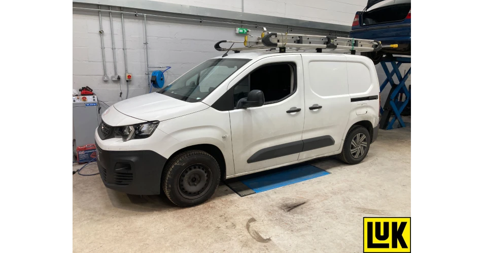
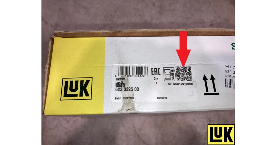 Fig 1
Fig 1
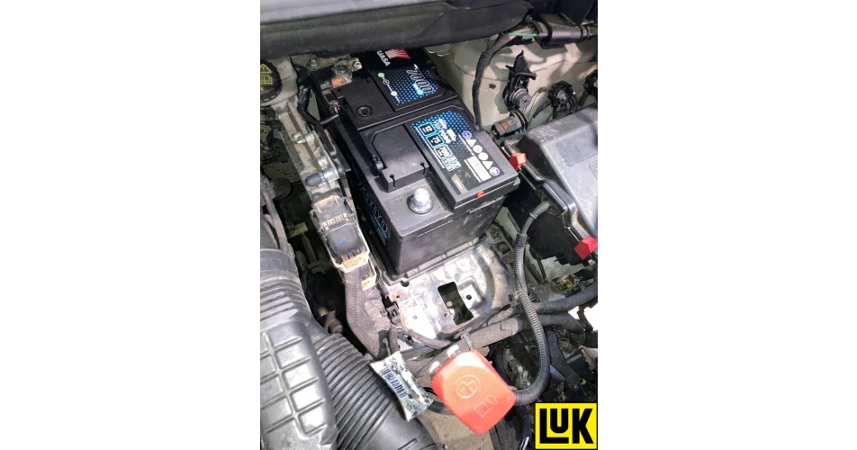 Fig 2
Fig 2
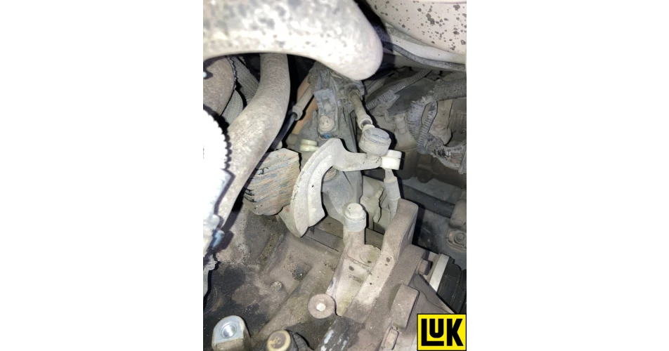 Fig 3
Fig 3
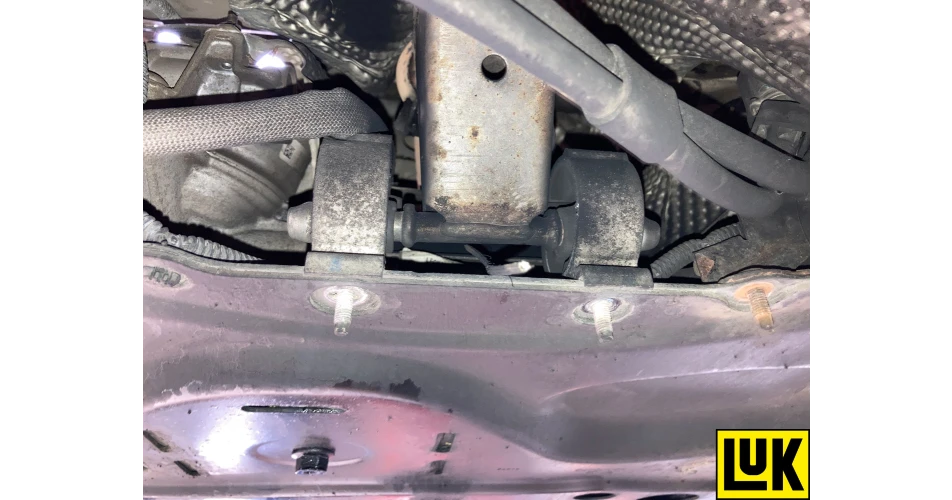 Fig 4
Fig 4
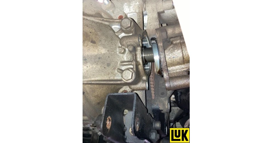 Fig 5
Fig 5
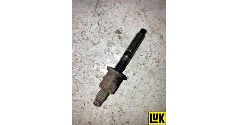 Fig 6
Fig 6
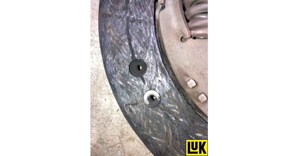 Fig 7
Fig 7
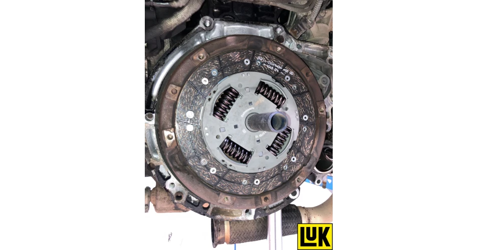 Fig 8
Fig 8


.jpg)
.jpg)
.jpg)

.jpg)
.jpg)


