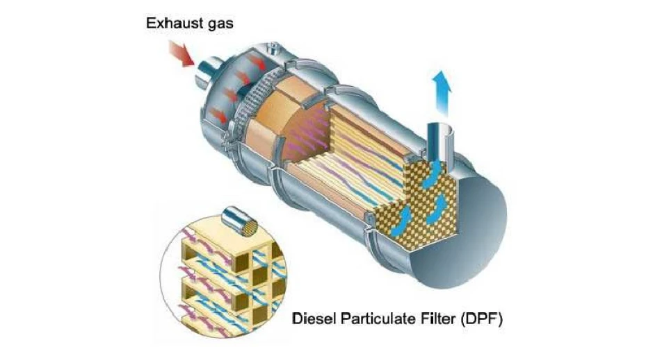
The Diesel Particulate Filter (DPF) was introduced in 1985 by PSA, to reduce the emissions from road vehicles. The particles emitted from poor or incomplete combustion have been attributed to respiratory health, so the design of particle filters has gone through various phases of development to improve efficiency.
In the beginning, the filter had a catalyst fitted in front to raise the temperature of the exhaust gas. This helped burn off the small particles of carbon, helping to keep the filter from clogging. A differential pressure sensor, with ports mounted in front and behind the DPF, monitored the pressure difference within the filter. This was used by the ECM to calculate filter load, and to determine when a regeneration was required.The regeneration raises the internal temperature above 600 deg C, which is when carbon particles will begin to burn off and pass through the filter. The construction of the DPF is generally of the wall flow design and closed at alternate ends. Only particles small enough to pass though the wall, around 1 micron, will pass through. The material used for construction is normally Cordierite, which has excellent thermal properties and good filtration properties. Relatively cheap to produce but has one drawback, a melting point of 1200 Deg C.
In PSA designed systems, they introduced a fluid into the diesel. Every time the fuel tank is filled a small quantity is injected into the fuel tank. This lowers the temperature at which the carbon particles are burnt off, reducing the frequency of when a regeneration is required. But this fluid is a service requirement to refill the storage tank at pre-set mileage intervals.
The differential pressure measured during normal operation is very low, around 10 millibar @idle to around 180 millibar at full load operation. Using this pressure information, the ECM can calculate the carbon load within the DPF. This can stop regeneration if the carbon level reaches 49 grams/ltr.
Temperature sensors are mounted at both ends of the DPF to monitor the safe working temperature during normal operation and filter regeneration. These sensors are normally positive co-efficient sensor technology, meaning that the resistance of these sensors increases as temperature increases. They may not read until they reach a predetermined temperature, usually above 100 deg. C. The DPF is normally supplied with a 5-volt signal and sensor ground. The signal voltage increases with temperature.
Some systems also include a vaporiser or an injector upstream of the DPF, which incorporates a glow plug and injects diesel into the exhaust gas stream. This is used to increase the temperature of the DPF for passive regeneration. One of the main failures of this vaporiser is the carbon build up blocking the fuel outlet. The most common symptoms are a failure to reach a high enough temperature to regenerate the DPF.
And more recently, a new addition to the DPF sensor array is the particulate matter sensor. This sensor is mounted after the particle filter to monitor the particle count passing through the filter.
Another temp sensor to monitor the DPF
Often DPF temperature fault codes can be mistaken for individual temp sensors being at fault. But this matter sensor has a combined temperature sensor incorporated internally in the DPF. Technical bulletins have this noted as a problem.
So, we started measuring pressure and temperature, and now we are measuring particle count.
To see or download this article click
here. There are lots more Tech Tips to view, and they are all searchable, on
TechTips.ie.
To join the Autobiz Helpline, call 01-905-9500, and then press 2, for further information.

