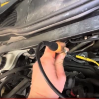
Use a 12V test light to load a circuit when you are testing the voltage on that circuit
Share:
A customer recently brought their 2014 Volvo V40, equipped with a 1.6L diesel engine, into Kennedy’s Garage because the Check Engine light was on. The V40 had about 186,000 kilometres on the clock, and was running normally, even though the Check Engine light on the dash, had been on for a considerable amount of time and miles.
My first step was to verify the complaint. The Volvo’s Check Engine light was on, and a quick scan revealed one significant trouble code stored in memory, P0238 (Turbocharger Boost Sensor A Circuit High). Although the code had been present on the Volvo for many miles, there was no problem with the way the engine was running.
The next step was to verify the fault using live data. Manifold absolute pressure data was accessed through a scan tool as the engine was running. The manifold absolute pressure was observed at 250kPa, at idle. As atmospheric pressure is always around 100 kPa, it was obvious to see that the sensor was reporting high pressure, and was the reason the Check Engine light was on.
A visual inspection under the bonnet didn’t show anything out of place that would cause this fault code. One of the air intake hoses was cracked on it’s exterior, but it hadn’t failed yet, as the interior of the hose was still intact.
A wiring diagram was found for this V40. The wiring diagram identified the number of wires attached to the sensor, as well as their colours. My reference also provided the expected voltages at the three wires from the sensor that provided the ECU with the manifold pressure data. According to my reference, the signal voltage from the sensor should have been approximately 1.6V at idle and 3.3V after a snap acceleration.
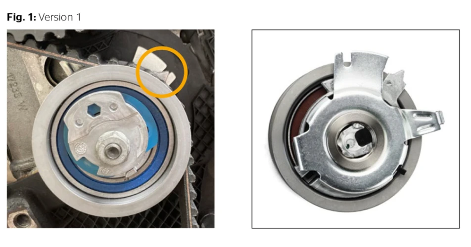
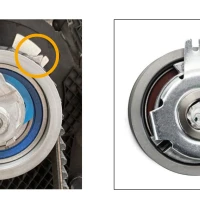
The sensor, and it’s wiring, appeared to be in good condition. The sensor had four wires connected to it, one for a ground, one for the 5V reference, one for the boost pressure signal and another signal wire for what was most likely the inlet air temperature.
A multi-meter was used to verify the voltage at each one of these wires, by back probing the connector while the engine was idling. The ground and 5V reference wires were spot on. Voltage was also checked while a 12V test light was loading the circuit being measured. Load testing is important, to ensure the wiring in the circuit is in good condition. If you do not test a circuit voltage while using a load test, you may make or come to the wrong conclusion about a fault.
Voltage at the sensor’s signal wire was 4.9V at idle, much higher than the expected 1.6V. This clearly showed that it was the sensor itself that was faulty.
Once the pressure sensor was replaced, the Check Engine light went off. Voltage at all of the lines from the sensor were re-checked. The 5V reference and ground were perfect, and the pressure signal wire was now at the expected 1.6V at idle. The boost pressure in live data rose as expected, after a snap acceleration.
A video of this diagnosis and repair is shown below. This video, as well as many others, can be seen on Kennedy’s Garage YouTube channel.
To read more of this technical article or download the entire article click here.
There are lots more Tech Tips to view, and they are all searchable, on TechTips.ie.
 Use a 12V test light to load a circuit when you are testing the voltage on that circuit
 Peter Kennedey, Kennedys Garage, Portlaw

.jpg)