Vacuum testing has been a major diagnostic tool, ever since the internal combustion engine was developed. Many vehicle systems rely on pressure and vacuum to operate correctly. With modern engine technology, the data received from pressure and vacuum sensors, is vital for correct operation of many systems.
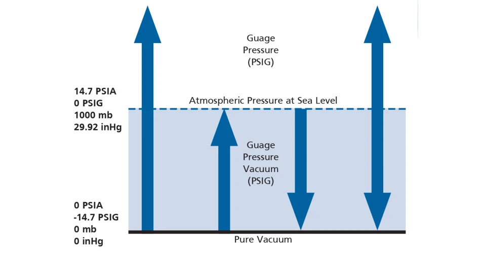
It is vital to understand there are two variations in pressure sensors.
Type 1: Gauge pressure sensor. This will read zero with no pressure or vacuum applied. In other words, it reads the pressure above or below the atmospheric (barometric) pressure. It can read less than zero, if there is a vacuum or partial vacuum.
Type 2: Absolute pressure sensor. This will read the pressure present, including the atmospheric pressure. It can never be less than zero. MAP and Boost pressure sensors are typically absolute pressure sensors. They record atmospheric pressure, plus any pressure applied.
It important to test the sensor plausibility before moving on. A pressure sensor should read either zero, or the current atmospheric pressure, when no pressure or vacuum is applied. Keep in mind that barometric pressure changes with altitude and weather conditions. This can be checked online at the time of testing. A typical atmospheric pressure on a standard day at sea level would be 1013 millibars (mb).
Skoda Yeti 1.6 TDi with poor performance A technician was working on a Skoda Yeti 1.6 TDi, with reported low boost and poor performance. He had been trying to diagnose a low boost situation starting with leak checking on the intake system. Smoke testing did not find any leaks. His research online indicated the Boost Control Solenoid, or N75 Valve, was the likely cause. So, he replaced the N75 solenoid valve without any testing. This did not clear the issue.
He did notice that the turbocharger had been recently replaced, so did not want to replace the turbocharger again. He decided to call the technical line for some guidance.
We started with some basic pressure tests, actual boost data under full load condition. This only achieved 120 kPa (1200 mb) a mere 200 millibar increase over atmospheric pressure.
We asked for some vacuum readings at the turbocharger, this was only 6 inHg (203 mb), indicating low vacuum. The technician had already “tested” the vacuum to the N75 solenoid, and he said it was OK. The signal controlling the N75 was checked, and these proved to be normal. In a typical N75 boost regulating valve, battery voltage is controlled through a duty cycle to regulate vacuum supply.
We then turned our attention back to the vacuum supply testing again. This time we wanted actual values at the input to the N75. It became clear the issue was low vacuum from the vacuum pump. The technician had sampled it with his finger and thought it was enough. We explained there was no calibration test for his finger. He needs to be more precise with pressure testing.
To test the output of the pump, we removed the brake servo line. The test proved the pump was healthy, so the Servo was the issue. To confirm the repair, a vacuum of 25 inHg (846 mb) was applied to the input of the N75 and the output vacuum had risen to 20 inHg (677 mb). The boost was retested and now recorded a healthy 245 kPa (2450 mb) under load.
We also went through some basic pressure tests for MAP, vacuum system, differential pressure, etc., so next time he would have the information available for his diagnostic processes. This would have saved unwanted part replacement and prevented wasted time.
Audi Q5 2.0 TFSi with a P0171 lean code On investigation for long term fuel trim figures, it revealed a positive 23% trim adjustment, plus a MAF loss figure of 2 kg/H over expected readings.
We took a look at the vacuum level present on the engine oil dipstick, knowing this should be around 80 mb, or just below atmospheric pressure. As expected, with these symptoms and code, the MAP pressure of 33 kPa (20 inHg) was present, far greater than normal.
Disconnecting the positive crankcase vent module from the intake, and blocking off the intake port, returned the vacuum to a normal level of 80mb at the dipstick, and long term fuel trim returned to a normal figure. A figure of plus or minus 5% is considered acceptable.
This vent module is a common failure, but knowing what pressures should be present in the crankcase and accurately testing this saves a long diagnostic session.
This process can be crossed over to many vehicle brands. Some will require more disassembly, as the vent system can be incorporated into the top cover, or even the intake manifold. But the pressure testing process will still reveal any issues.
In all engines, the principle still remains the same, designed to separate oil from the crankcase emissions and allow the fumes to be recycled into the intake for reuse in the combustion process.
In some cases the vacuum will be so deep, that air can be drawn in through the oil seals and produce a distinctive whine. But will always produce a fuel trim error code.
To see or download this article click
here. There are lots more Tech Tips to view, and they are all searchable, on
TechTips.ie.
To join the Autobiz Helpline, call 01-905-9500, and then press 2, for further information.
 This graph shows the difference between Absolute & Gauge pressures
